Products / Screw Conveyors / Trough and tube screw conveyors

Trough and tube screw conveyors
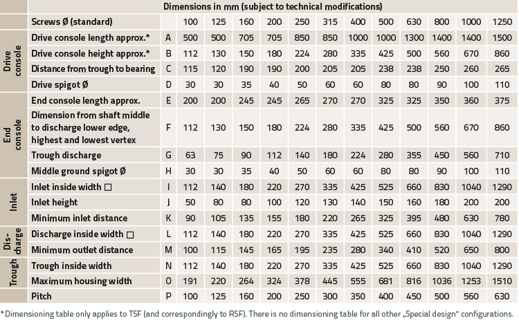
Design Data*
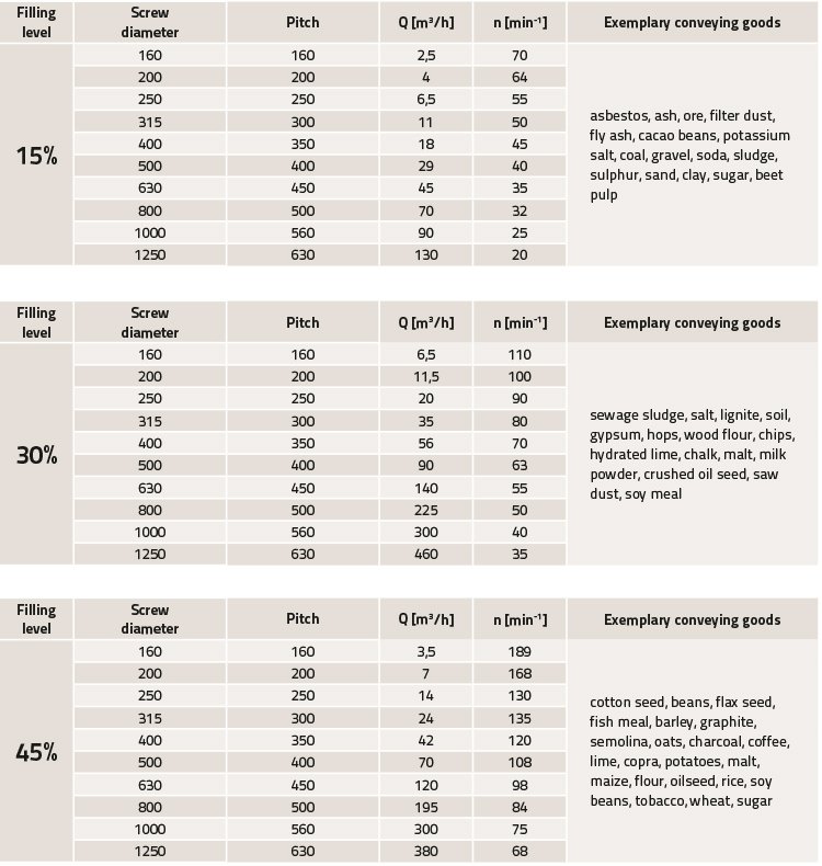
Theoretical conveying capacity in proportion to filling level
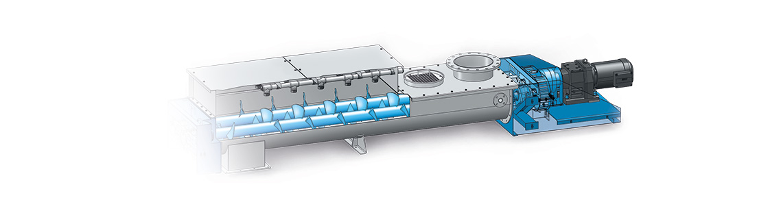
Screw conveyor construction modular system
- Driving console:
with shaft-mounted geared motor and torque support, with spear gear motor with coupling, pedestal bearing with gland nut, flange bearings with sealing ring
- End console:
pedestal bearing with gland nut, flange bearings with sealing ring
- Conveyor trough:
tube trough, V-trough, box trough, U-trough
- Inlet:
variable
- Worm shaft:
tubular shaft with blade or paddle, worm shafts without tubular core
- Outlet:
variable